Arduino Pong Clock with secondary MAX7219 7 segment display prototype
I made an alteration to the dual colour pong clock that I made last year. The clock shows various time modes on a 16x32 HUB75 compatible matrix display module but also has a separate 7 segment display. This shows the time during the night or when the "matrix mute" mode button is pressed which basically turns off the huge clock when you don't want it on.
However it never worked right; the second digit was always dimmer than the rest and some digits flickered when certain segments were lit or when the colons flashed. It was connected directly to the ATMega2560's pins via transistors using the sevenseg library but the matrix code was interfering with the library. The sevenseg library works best with a timer interrupt for multiplexing the display but that caused issues with the HUB75 driver.
So to fix this I altered the prototype to use a MAX7219 instead which required only 3 wires to the display excluding power instead of 12. It works much better but occasionally when the 7 segment clock is turned on the second two digits show the wrong information or weird combination of segments lit but this corrects itself after a minute or so. I think this is caused by the length of the cable from the control board to the display. I used a long cable so the display(s) would fit into a photo frame with the controller mounted to the back. But that may not work out and I may have to put it inside the photo frame like I did with the original.
I've also gone over the various modes just to show what this clock does.
This is a repair for a family friend who owns a watch repair business. The cleaning machine dates from the 1940's and has been sat in a damp place for a very long time. It was really just scrap when I got it as the casing was all rusty and the original electrical wiring with fabric insulation was rotten. It was a lethal shock hazard and a fire hazard too. Even if the wiring was in good condition the original design had all the mains live connections exposed including the rheostat that adjusted the motor speed. It's also not a good idea to have a flask of water sat on top of a live heating element...
Guess electrical safety wasn't a thing in the 1940's as this definitely would not pass any modern safety standards.
Upon inspection everything was knackered; the motor was burnt out and rusted, the heating element had gone. Even the switch was knackered. So to make this thing safe I decided to replace all the parts with 12 volt low voltage parts. The current drawn by the heating element could be a problem but I used a PTC heating element that draws a peak current of 4 amps.
To adjust the speed of the motor I used a cheap voltage regulator module off eBay which worked a treat. The only problem I had was with the motor; as the shaft of the original was an imperial size (somewhere between 6 and 7mm) I could not find a replacement. So I had a spare motor laying around from an old HP printer which had a 3.4mm shaft. I used a coupler 3mm to 6mm bored out at the 3mm end to 3.4mm on a lathe to fasten it to the impeller. A 6mm metal dowel was used however this was too small to fit the impeller. So it had to be packed out with tape.
This worked quite well but there is some slight wobble which I have corrected as best I could with the grub screws however it should not cause a problem once the impeller is inserted into water.
I thought about making a video after I'd started working on it hence the hasty recording on a phone but it should get the point across showing what I've done to restore this unit to working (and safe) condition. I also could do with a better microphone and camera but my phone will have to do for now.
Here I have another military hardware eBay find which appears to be a control panel for a video processing unit that takes the recorded video from a Tornado jet's onboard VHS video recorder (yes, really!) and exports it to another media format. It has several analog switches and consists of a keyboard with 7 segment displays showing the mission time etc.
It was made by GEC-Marconi Avionics (now BAE Systems) in the early 1990's and is called a "GRF Control Panel" which I think GRF is an acronym for GR Force - as in Tornado GR1 Force. But I'm not really sure. I asked BAE Systems about this unit but it appears to be something they forgot about or contracted it out and stuck their name on it. The boards say Tactus International on them as a clue. That company seems to be defunct.
Unfortunately it does nothing on it's own as it is simply a dumb keyboard and display assembly. Internally it is filled with CPLD chips and EPROMS which are used as combinational logic rather than for storing firmware. There's some ICM7228 LED display driver chips, a few 74xx series chips and that's about it. The CPLD chips could be possibly resold as they are expensive and obsolete and easily reprogrammed. The rest can go in my spares bin as I managed to control the LED display with an Arduino using the ICM7218 library which works with the ICM7228.
The whole thing runs off 5 volts so it was easily powered up and it communicates with the host system via a RS232 port which spits out a continuous stream of garbage. Hmm.
I dumped the EPROMS to a file and showed that in the video too. Might be of some interest to some as to what this thing is (I'm not really sure myself) but it will come in handy for spares.
See my electronics blog at adrian-smith31.co.uk/blog for more electronics stuff. I might do an article on this thing too.
Here I tear down a Line Replaceable Unit from a RAF Tornado jet fighter aircraft. A LRU is aviation speak for the black box(es) that sit in the avionics / equipment bay of an aircraft which contain the electronics for the various on board systems and computers.
The Tornado aircraft was retired from service in the UK's RAF last year (2019) being replaced by F35's and Eurofighters. The box dates from 1978 / 1979 as it is part of the original avionics suite when the aircraft was put into service. They had an avionics upgrade circa 2000 I believe where the cockpit instruments were replaced with LCD displays rather than analog dials and the navigation system (TARDIS) updated to full colour high resolution LCD's. Now presumably the LRU's were replaced too; I highly doubt there were 1970's electronics still in use onboard an aircraft in 2019!
*** UPDATE*** Yes, they were using some of the original avionics up until the aircraft was retired. I found another interface unit on eBay that had the service documentation with it stating the fault and the aircraft it was removed from. It was removed and replacement LRU fitted to the aircraft in September 2018.
It is very well engineered and consists of 14 circuit boards that plug into a backplane consisting mainly of analog circuity such as comparators and op-amps with several other boards containing 54 series TTL (military spec of 74 series TTL) which from what I gather form a interface between various sensors and the main computer of the aircraft.
This is an" interface 1" LRU; the Tornado had two interface units presumably connecting several systems and sensors to the main computer. The circuit cards contained inside of the interface 1 LRU depends on what model aircraft it came from; there were several variants of the Tornado such as the GR1, GR4 and ADV. I believe this came from the ADV variant as I found the same unit on ebay with a slightly different part number which mentioned the particular aircraft it came from. That was a GR4.
Speaking of the main computer I managed to find out that it does not have a CPU, rather it is discrete consisting of several boards packed with TTL logic gates. The avionics were designed in the early to mid 70's when microprocessors were in their infancy. Unfortunately there isn't much information on any of the Tornado's avionics, sources I found were a forum with former service technicians contributing and the Rochester Avionics Archive over at BAE Systems. There are several sellers on eBay selling various Tornado parts. Beware though when buying electronic modules; a lot have had their guts removed so they are literally empty black boxes. The sellers fail to mention this.
Anyway, if you do have any information and / or any comments please comment below. Also visit my blog at www.adrian-smith31.co.uk/blog for a detailed article and high resolution photos of the circuit boards.
Finally, you may be wondering what on earth I'm going to do with this thing. Well it's made of high quality aluminium and if all the electronics are stripped out it would make a great project box. I have a high current power supply project in mind and this would make an unique case to put it in.
The PCB's I will either dispose of or sell on eBay. If anyone is interested in purchasing them or the box as a whole, let me know. That will have to be quick though as I will be getting rid of it eventually. It weighs a ton and takes up space. It was bought really as a curiosity item and it was fairly cheap.
If this video is a success, I may do other obscure electronics teardown videos. I just need a source of cheap and / or useless obscure crap for me to tear apart.
I've got a little project in the works which is a 4 digit seven segment display board using a couple of 16 bit shift registers with built in constant current LED drivers. I have a lot of these chips and have been unable to offload them on eBay. So the plan was to use them in a project I could sell as a product instead.
However they are surface mount in SOP24 package and with me not working at the moment I don't have access to a hot air soldering and rework station. Bummer. Well I could buy one and done solder paste but that's just extra expense for a handful of one off boards. So I decided to hand solder them instead using an ordinary soldering iron.
Had to use flux - very important if you want a good solder joint with no shorts between pads.
Not a bad attempt if I don't say so myself. If anyone is reading who is interested in how to solder SMT parts without hot air watch on...
I picked up an aircraft black box that came from the failed Nimrod MRA4 project that was picked up cheap on eBay. The "black box" is actually bright orange and has reflective striped across the casing. It is around 20 years old (manufactured 06/2000) and utilizes solid state recording using flash memory as the storage medium.
I was interested to see if I could extract any data from it but unfortunately that was not possible although I was able to power it up as it only needed 28V dc to work. It made for an interesting teardown anyway and now would make a suitable man cave item.
The internal circuit boards consist of a power supply board, an audio processing and compression board, the main CPU board and the flash interface board. The CPU board has two microcontrollers; an 80C51 and an AMD 29200 along with flash memory, ROMS, RAM and the usual stuff. I also dumped one of the ROMS and managed to extract some of the serial menu from the code that is sent over the RS232 port on the front.
This will probably be my last avionics teardown video as the videos are not as successful as I thought they would be and I don't make any money from this channel. The gaming videos were a waste of time so I won't be doing much if any at all of those. Some of the past items I have tore down I have resold on eBay for profit but remains expensive to buy such items. I will see what I can find in the future and hopefully I'll come across something cool for a reasonable price I'll be able to resell or re-use for parts after I've done making the video. I might revisit some of my previous teardowns of avionics I've decided to keep as one suggestion was to turn the Merlin Helicopter CDU into a jukebox which sounds like a pretty cool idea if I can pull it off. A raspberry pi and a touchscreen LCD should do that nicely. Hmm.
Photos of the internal electronics can be found on my blog at adrian-smith31.co.uk/blog
Timestamps:-
Part 1: Teardown of control electronics 4:00
Part 2: Teardown of audio storage module 12:05
Part 3: ROM dumping and a look at the code 18:15
I was given another watch cleaning machine to repair but this time it wasn't as ancient as the 1940's era machine I repaired the other month. I guess this was from the 1960's but it was still a massive electrical shock risk. Electrical safety standards did improve from the 1940's - they put a metal cover over the electrical connections and controls. That's it.
As it was it still left water and cleaning chemicals to be splashed all over the exposed wiring and controls live at 230V with no earth in place. The wiring was all corroded and rotten, the motor was knackered and the heating element so rusty and corroded it just disintegrated. So to make this thing safe like the last machine I stripped it down to the bare chassis and threw everything else in the bin. I then gave it a good clean with dish soap as the cleaning chemicals left a sticky, smelly residue all over the place. Some of the paint came off when I cleaned it so I repainted the base.
The second part was replace it all with low voltage 12-24V components which you can see in the video. The controls I moved to a waterproof box fitted to the front of the machine over where the old control panel was. The only exposed wiring was to the heating element but this was insulated and waterproofed later.
Inside the box there's just a motor speed controller, a switch and an LED. Originally a 50 watt wirewound 2K potentiometer was used to vary the AC motor speed. I brought it into the 21st century by adding an electronic controlled speed controller although it was DC rather than AC.
This video probably won't interest regular viewers but it's a demo for the guy who owns it as well.
Parts used:-
Motor https://www.amazon.co.uk/gp/product/B07S6L9CT6
Drain cover https://www.amazon.co.uk/gp/product/B00VITUIZO
Speed controller https://www.amazon.co.uk/gp/product/B06XHGP58T
PSU https://www.amazon.co.uk/gp/product/B07VQYPJW8
Connector https://www.amazon.co.uk/gp/product/B07PDXG3BT
Heating element https://www.ebay.co.uk/itm/DBK-HP03-1-08-24-HEATER-PTC-F-PLATE-30W/173530709887
Box https://www.ebay.co.uk/itm/WATERPROOF-PLASTIC-ELECTRONICS-PROJECT-ENCLOSURE-CASE-COVER-JUNCTION-BOX-IP55/302502060574
Plus other misc bits I had in my drawer such as block connectors, cable and fixings.
A short video today which isn't a full teardown rather than looking inside the CRT cockpit display for the Radar Homing Warning Receiver unit that warns the pilot of incoming missiles and other threats.
It is 1970's design and consists of a green screen CRT which is a vector scan type display; there's no video signal processing inside so it won't take a video input. It needs several voltages to work along with the X and Y signals and the beam input. I did try and power it but accidentally blew up two of the transistors shown in the video. It won't work on just 28V DC.
Also the CRT is encased in a silicone sealer rubber type material which makes removing it difficult. The unit would have to be wrecked and the CRT could get broken so it was a bit of a disappointment as I thought I might be able to make something with it. A possibility could be drive it from an Arduino with the scope clock kit PCB or similar. However seem as this does not use a oscilloscope type CRT, rather a conventional CRT instead it isn't really possible. The CRT uses magnetic deflection rather than electrostatic and has 6 coils around the tube from what I can measure with my multimeter. The scan coils are not accessible due to the encasement of the CRT in that rubber material.
Shame I couldn't get it to power up nor get it to display anything. I tried reverse engineering the display but it just wasn't worth it in the end.
It's something to keep for the man cave or resell on ebay by the looks of it.
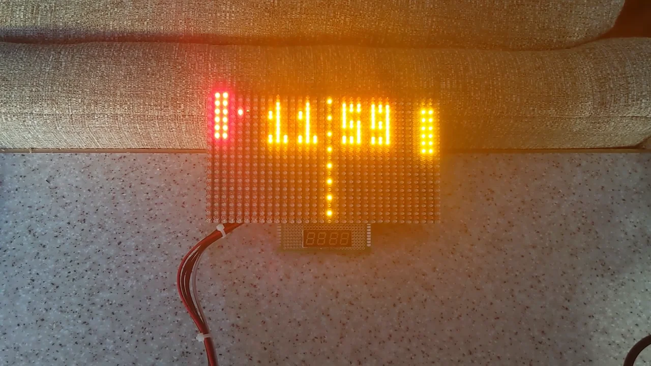
I managed to come across some salvaged LED display modules from a large LED display board on ebay. A little digging reveals that it originally used in cinema lobbies for displaying movie titles and showing times. I bought one to experiment with and see if it could be driven from an Arduino as I had some time on my hands with the covid19 lockdown.
The main controller board was missing and there was no datasheet so I had to do some reverse engineering. The data input is via a 14 pin connector and there is another at the opposite end to daisy chain to the next module.
The 7 rows are driven through a 74HC373 latch used as a buffer then to a mosfet driver IC. The 60 columns are driven by MIC5821BN high power shift registers. This is a fairly standard setup and was relatively easy to get working the only complication being that the row data logic needed to be inverted. Also the way the shift registers work is a little different to the fairly standard 74hc595 and they don't work on higher SPI speeds where the '595 will.
With some sample code I was able to get the display to work and modified the code to accept new messages sent via serial and store them in eeprom. It can serve as an advertising board or adapted to display the date and time as a trendy clock for example.
I bought one of those cheap Finrsi tablet scopes from Amazon as I needed a cheap scope to use very occasionally for basic things. Obviously I didn't want to spend a lot of money so this seemed ideal for me and the portable tablet form is quite appealing.
Now a pro engineer would not entertain purchasing one of these but for a hobbyist they should be fine. However I did run into a few issues with it as in the general quality is so-so and the operation of the unit isn't without it's problems.
Since making the video I would like to mention that the bandwidth is only 5Mhz on the 1x probe setting and supposedly 100Mhz on the 10x setting. I should have read that Chinglese manual. Doh. However the bandwidth is really around 20 - 25Mhz as you will see. I do encounter a lot of interference and ringing even at low frequencies which I believe is partly the scope. It does pick up noise even when nothing is connected which is kind of normal for digital scopes but more expensive models have various ways of reducing this. It also seemed to have trouble triggering from the internal 1khz calibration signal.
***The 50% auto trigger can be turned off in the system settings (I found this after encoding the video) and turning this off makes a vast improvement making the scope more usable. ***
The trouble is I don't have any lab quality test gear; I can only compare this scope's performance with an older and more expensive model. I'm also used to using CRT analog scopes however the scope I use at work is a digital scope around 6 years old. I did use the same equipment to test this scope that I used with the scope I borrowed from work and didn't encounter any of the issues shown in the video if that's anything to go by. My Keysight DMM has a frequency counter built in so I was able to verify the accuracy of the scope's frequency readout which is spot on. Voltage wise, no. It's out by nearly half a volt with a 5V p-p signal input.
Would I recommend this? Well depends on what you want to use it for. Basically if you want this as an instrument that can give accurate, reliable readings then no. The voltage measurement readings are way out for a start.
However if you just want to check for presence of a signal or not or want it for audio use and possibly TTL logic / CMOS circuitry then maybe, yes it could work for you. But I really would save up and get something better; you need to be spending at least £300 for an entry level scope.
It's a shame really as the tablet format is really good as it's portable and much easier to use on the bench without having wires everywhere. I really want to like this little scope but I just don't want to trust it. Maybe it will get future firmware updates but there doesn't appear to be any way of easily doing this unless possibly it's updated via USB? Something I could look into.
***Further update***
I've since changed my mind about sending this back. I may look at adding some sort of shielding and do some further testing with it as I believe it isn't that bad just not that good either. But there is always some doubt in my mind if this thing is showing me the right readings or not. I'm aware the voltage readings are high but I can account for that.