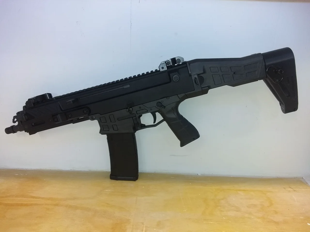
Bren 2 Brace! Designed for use with my Bren 2 Brace Adapter, but can also be used on a standard AR buffer tube.
NOTE: This is a heavily modified remix of the CTRL+PEW Brace!
Features attachment points for up to a 2" sling, or a QD mount. Ratchet action uses a ball bearing (optional) to click into place.
The thin profile of this brace enables the factory Bren folding mechanism to correctly lock in the folded position. The original CTRL+PEW brace was to thick side-side to enable the latch to catch.
Parts List:
1x M4x16 screw >> If you're using the solid brace adapter, you will need an M4x40 screw instead!
1x M5x25 screw
1x M4 nut / nylock
1x M5 nut / nylock
1x 3/16" spring washer
optional:
1x 5/32 chrome ball bearing
1/2 ballpoint pen spring (or equivalent)
The ball bearing is OPTIONAL because you can just tighten down and the friction of the spring washer will hold it in position, depending on your preference.
I found printing with a brim and tree supports works better, but you still have some cleanup to do after the supports are removed. A bit of careful sanding with an emory board, small file, or simply scraping with a hobby knife should clean it up.
The pics show how to install the M4 nylock washer in the hollow of the brace adapter. Simply install it without the brace, and it will get drawn into the cutout. Then you can assemble the parts with the screw being careful not to force the nut back out. Using a magnetic pick-up tool will greatly simplify installation of that nut!
I've tested the hinge to breaking, and at 50% infill / 0.1 resolution, you have to REALLY crank down to break it. As in, leaning fully on the hinge to crack the plastic. So for NORMAL use, it appears to be more than strong enough at 50% infill. You can of course add more infill depending on your preferences :)
When using my brace adapter, Length Of Pull (LOP) is just at 12.5 inches, below the "recommended" max of 13.5 inches.
This brace will also fit on an AR buffer tube as in the pic. You can replace the M4 screw with an M4 "soft tip" set screw - the kind that has a plastic tip. This will avoid damaging the finish on the buffer tube! If it proves too tight to fit on your buffer tube, you can lightly sand the interior to get it to slip on. OR you can increase scale to 101% and reprint.
Thanks to CTRL+PEW for the original buffer tube design!
Print Settings:
0.1 || 4 perimeters || 50-100% infill || Tree supports || PLA+ (eSun or equivalent) || Brim/Raft depending on need
Siderail with holes aligned to enable clearance for the charging handle when using lights on the left side. Supports required for the M-Lok clips on the back side. Optionally, you could move the model down in the sliders to be flush on the build plate to delete the M-Lok clips.
Hera grip! I took the existing model and added:
- Replaceable inserts: 3 styles with different textures: smooth, stippled, and hex stippling
- QD release points
- Smoother thumb/web grip area
- Recess for M3 screws/nuts spaced for standard Picatinny mount
"Improved" 300 Blackout jig!
Based loosely on 300 jig by jmynheir on Thingiverse!
I mounted mine on a piece of 2x4 that is attached to a base piece of plywood I screw to the table with 1/4" inserts and hand screws. Makes for a very sturdy platform. I wanted to connect the jig directly to the cutting tool bed, and be able to align it. Made for standard M4 screw to use the cutting tool's alignment nut, with a pointer to help with squaring it. I was able to get it aligned down to 0.1mm side-side.
Tapered jig - I added a 0.1mm taper to make the cuts more square than a typical BO jig. Using calipers, I'm able to confirm this jig makes a more squared cut with much less angle.
Adjustable - threads in back to use a 1/4" or M5 screw to make incremental adjustments to the cutting length. Cuts above 1.385" without any adjustment, and can be adjusted shorter depending on your needs. Note that published cast trim length is 1.358.
Discard tray is optional - the attached pic shows how I put a box around to collect brass shavings. The tray is short enough that you can push the cardboard under the tray.
UPDATE:
=======
- New maingear that uses metal hub. I found I had to modify the main gear to accommodate a 6mm Flange Coupling Connector. Found the "6mm Flange Coupling Connector" on Amazon in a 4-pack. This will eliminate the issue with the maingear stripping off of the D-shaft if too much torque is applied.
- Added lid.
- Bearings are "608" bearings which are "8mm x 22mm x 7mm" skateboard bearings. I got a 20-pack from Amazon. You'll need 12x for the build!
Tool posts uses 8/32 brass inserts, Lyman case prep tool inserts, and standard gun cleaning kit brushes.
Based on "Brass Prep Station" by msgbean as found on Thingiverse!
Tool posts uses 8/32 brass inserts, Lyman case prep tool inserts, and standard gun cleaning kit brushes. Project files will be available on Odysee, Thingiverse, and Printables
8/32 brass inserts can be found on Amazon under the brand name "E-Z Lok" and should also be available locally.
8/32 flathead screws hold the top assembly, and standard hex head screws hold the top and bottom halves. You could easily use any standard screw you had available for all but the tool post inserts. Don't screw the upper portions (with the bearings) too tightly, otherwise the friction will cause the motor to stall.
M5 screws and inserts *could* be used for the assembly if you have some of those available, but you will still need 8/32 inserts for the tool posts. I purchased a 100-pack of 8/32 brass inserts, so I had enough inserts available to add extra tool holder storage spots on the sides. You can drill out the holes for extra tool holder storage without inserts.
Tool post alignment - it seems the tolerances in the assembly allow for tool holder wobble. You will have to adjust the tool post if it spins erratically. I had to do this for several. Use a soldering iron to heat the insert, then pull against the most erratic point of the spin. This will re-align the brass insert and will make the tool spin more true. I was able to tweak the inserts until the tools spin "true".
I used the 200 RPM "Geartisan" brand motor. The 100 RPM just didn't cut it. Motor brand will not matter so long as it has the 6x M3 mounting holes. I used M3x8 screws. The motor MUST be wired "backward" to make the tool posts spin in the correct direction! (e.g. the positive wire needs to be attached to the negative terminal, and vise-versa for the other wire).
Maingear additional hub is intended to be screwed into the main gear to provide a mounting surface coverage for the exposed motor shaft. I was having problems with the motor pulling loose from the main gear during testing, since there is no grub screw to hold the main gear against the D-shaft. This extra hub simply provides more surface area for the main gear to stay connected to the motor hub to avoid any torque-related issues.
I found a 2-pack of 12v 2 Amp power supplies, which I suspect the extra amperage was also helpful in making sure the mechanism works during load.
I had an illuminated automotive rocker switch available so I used that... any switch will work! There's provision for an LED bezel on the main box.
The teeny little shaving collector is optional.
Removed A2 carry handle and managed to recycle the parts into this basic configuration. Pics show the only parts required. Uses M3 screws to secure to the rail. Fit is snug so M3 screws are fine.
Modification of BrewNinja's ARK Charging Handle. This one is for the "DIY" Upper in the ARK files. Changes include:
- FIT for the "DIY" Upper!
- Enlarged handle cover for an easier grip
- Main contact area is hollow to allow insertion of a screw for reinforcement
- Beveled surfaces so it works properly within the DIY upper with no binding\sticking when in use
- Altered height of main assembly for proper clearance within the upper assembly.
- Room for an optional ballpoint screw detent: this will require addition of a detent "pocket" on the upper to accommodate